Constructing and Using a Drip Flow Reactor
Instructor Version (go to Student Version)
| Subject Area(s) | Microbiology |
| Intended Audience |
Middle school science, high school biology, introductory undergraduate microbiology |
| Type | Laboratory Exercise |
| Revision Date | November 13, 2009 |
CONTENT
In their classic book Biofilms, Characklis and Marshall describe three general types of reactors, Batch Reactors, Continuously Stirred Tank Reactors, and Plug Flow reactors1. Each has its advantages and drawbacks. A culture in the batch reactor undergoes a typical growth curve and conditions change as cells accumulate and nutrient and waste product concentrations change. The CSTR2 is a prototypical chemostat with nutrient input and waste output ports. Conditions in the CSTR can be adjusted so that cell number, growth phase and nutrient concentrations remain constant over extended periods of time. Once a culture is established on a coupon* the medium flow rate can be increased so that the culture “washes out”. Subsequent growth is confined principally to the walls of the reactor and the coupon surface. CSTRs are very useful, but not particularly prototypic of many naturally occurring sites where biofilms grow in part because of the high shear caused by the impeller that stirs the culture medium.
* a removable surface placed in the reactor as a substrate for the growth of cells.
To visualize a Plug Flow reactor, think of a pipe through which medium is flowing or a surface over which a medium is dripping. The biofilm culture is stationary and the medium flows past at a rate that may be variable and variable in nutrient concentration. The Plug flow reactor may be closed channel, such as a pipe, or flow cell3 or open channel as in a toilet bowl surface, a riverbed or a rock wall seep (Figure 1. Note that the biofilms begin at seeps in the cliff as the water emerges from the rock wall and flows downward. The Anasazi site shown here is called White House and was occupied prior to the 1300s.).

The drip flow reactor that can be constructed from these instructions is intend to model the many aerobic habitats in nature with relatively low nutrient flow and low shear conditions.
PREREQUISITES
Students should be able to define the term biofilm, describe the differences between biofilm (surface-attached) and planktonic (free-floating) bacteria, and describe why bacteria tend to grow on surfaces and how they are different from planktonic cells. If the student is to construct and use this Drip Flow reactor they should have a basic working knowledge of power and hand tools and knowledge of basic microbiological techniques such as transferring cultures, aseptic technique and laboratory safety.
INSTRUCTIONAL OBJECTIVE
A Drip flow reactor is a device used to model many types of biofilm forming enviroments involving a flowing medium usually with a low shear factor. The biofilm is established on a glass slide coupon. Medium enters drop by drop at the upper edge of the slide and flows over the growing biofilm, exiting at the bottom of the reactor. This diagram (Figure 2) shows a very early version of a Drip-flow reactor used at the Center for Biofilm Engineering. The reactor itself was a plastic Petri dish, simple and inexpensive, but, with only one test channel, it wasn’t very versatile. The medium in this case was delivered to the reactor by a peristaltic pump (P) but gravity flow can also be used.
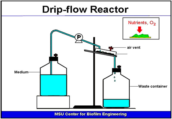
The Drip Flow Reactor shown here (Figure 2) was designed to reproduce the characteristics of an open channel plug flow environment. It is prototypical of a large number of natural biofilm producing systems and opens many possibilities for investigations at the precollege or undergraduate level. This exercise gives instructions on how to build a Drip Flow Reactor from commonly available materials. Each reactor can be built for less than $ 40.00. Although the reactor shown cannot be autoclaved, it can be disinfected in 10% Clorox. For many useful exercises sterility is not required.
Note on safety: In these exercises it is recommended that only BSL 1 (BioSafety Level 1) organisms be used or that the reactor be connected to a source that can bee deemed safe, tap water, an aquarium etc.
CONSTRUCTION PROCEDURES
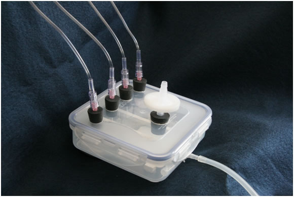
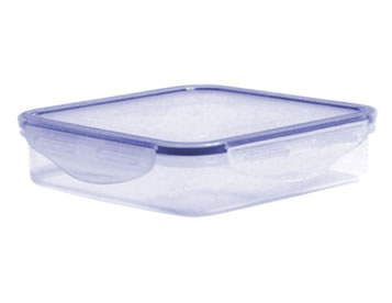
Heritage Mint manufactures a line of plastic storage boxes with a unique lock down lid with built in O-ring. The dimensions of this particular container are sufficient to hold four 1 x 3 microscope slides side by side (5.3" square x 1.8" tall). This container is ideal for making a Drip Flow Reactor that may be used in undergraduate or precollege research applications.
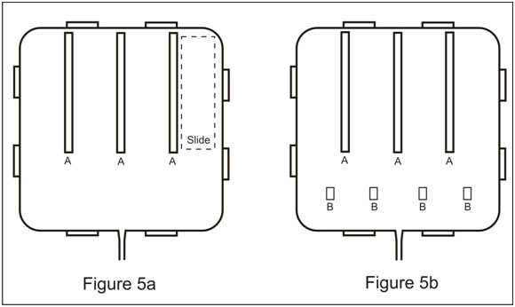
Step 1 is to divide the bottom of the Box into 4 sections each of which will hold one standard microscope slide. Cut 3 x 4” lengths of ¼ “ square plastic stock, sand the ends of these pieces smooth with sand paper. Position these plastic pieces in the bottom of the Box as shown in the diagram Figure 5a. The upper end of the dividers should be in contact with the upper edge of the Box. Using aquarium cement applied to the bottom of the dividers, cement the 3 dividers into place in the bottom of the box. Use sufficient cement that the excess squeezes from beneath the plastic strips so that there are no open crevices. With a utility knife, clean up any excess cement that squeezes out from under the dividers. Using a microscope slide as a template, make sure the dividers are spaced evenly. You now have 4 roughly equal spaces (test channels) for inserting 1” x 3” microscope slides to be used as coupons.
Placement of dividers and stops.
Step 2. In use the reactor will be tilted at an angle of about 10o. If not held in place the slides will slip to the bottom of the reactor. Cut 4 pieces of ¼ “ square plastic stock ½ “ in length. Sand the ends of these pieces smooth with sand paper. Then as shown in the diagram (Figure 5b), and using the aquarium cement, glue these pieces in place at the lower end of each of the test channels to hold the slides in place during treatment. Permit the cement to cure for 24 hours.
Step 3. Mark a line across the top of the Box lid at about 1” from the top as shown in the diagram (Figure 6). Place a mark on the line directly above the center of each of the test channels. Using a scriber (or a nail) mark these spots for drilling. Place a ¾” paddle bit in the chuck of a drill press. Place the Box lid on a board on the table of the drill press. Holding the Box lid firmly, gently bore one hole at each of the marks you have made. These holes should be just the right size to hold a # 00 rubber stopper.
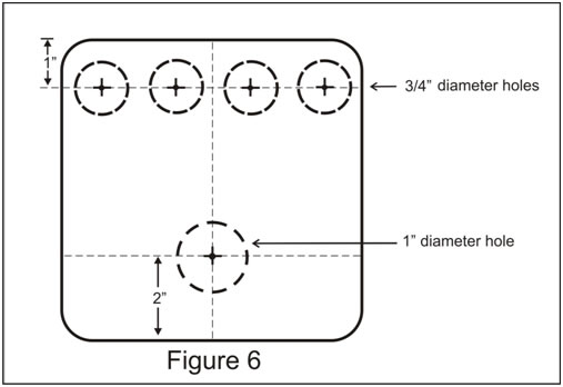
Step 4. Find the center of the Box lid and draw a line from top to bottom (at right angles to the previous line Figure 6). At a point 2 inches from the bottom of this line make a mark with the scriber or nail. Using a 9/16” paddle bit, bore a hole at this point. This hole will hold a # 1 rubber stopper.
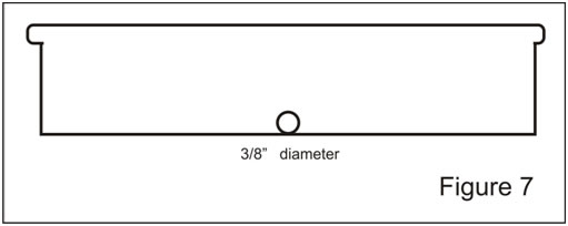
Step 5. Find a double barbed connector fitting about ¼ “ in diameter and cut off one end. Using a ¼ “ drill bit in the drill press, bore a hole in the base of the Box as close to the bottom of the Box as possible. Insert the cut off end of the connector into the hole and cement it in place with the aquarium cement. This will be the drain port for the reactor.
Step 6. Obtain from your nursing department or order from a medical supply house 4 Insyte Autoguard IV catheters and 4 Standard IV tubing sets each with 1 Y-site, for each reactor you intend to make.
Step 7. Insert a # 00 one-holed rubber stopper into each of the 4 ¾ “ holes and a # 1 one-holed rubber stopper into the 9/16” hole drilled earlier.
OPERATION
Step 1. The drip flow reactor can be disinfected if necessary by dipping the bas and the lid separately in a container of 10% Clorox solution for 5 minutes. Remove the components with a pair of tongs permit them to drain and then rinse them in a container of Sterile Distilled Water. Drain the top and bottom and assemble the reactor aseptically. Caution: Vinyl gloves and protective apron and goggles should be worn during this process.
Step 2. The culture is established on the pre-sterilized slide in any of several ways. The slide may be suspended in a culture of the desired organism or in an aquarium. It may be located in a pond, or stream for a day or so. Or the culture may be added to the slide lying flat in a sterile petri dish. During this phase cells adhere to the slide forming a nascent biofilm.
Step 3. The slide is now placed into the Drip-flow reactor and the reactor is assembled and attached to a nutrient supply fed by gravity or peristaltic pump. Incline the reactor at an angle of approximately 10o. Use molding clay or plasticine to hold the reactor in place.
Caution: it is a wise precaution to place the reactor in a basin larte enough to hold the entire contents of the reactor and nutrient source in the unlikely event of an accident.
Step 4. Remove and discard the metal needle from the Insyte Autoguard IV catheter and dispose of it in a sharps container. Attach one Insyte Autoguard IV catheter into the Luer Lox end to the IV tubing. The flexible end of the catheter is inserted into the hole of one of the 4 x 00 rubber stoppers. Repeat this process for each test channel you intend to use.
Step 5. Insert an Air Vent into a rubber stopper and place it in the 9/16” hole drilled for this purpose.
Step 6. Attach the IV tubing sets to the nutrient source and adjust the flow rate with the adjustment device. Make sure the waste tube is directed to a container sufficiently large to contain the entire volume of the nutrient supply carboy.
Step 7: Caution: When handling coupons be sure to wear vinyl gloves and gowns to prevent any possible contamination
EXTENSIONS
The biofilm population once established on the coupon can be used in any number of follow up protocols.
a. It may be stained using Gram’s stain or the modified Flow-through Gram staining technique give some indication of species diversity.
b. Extracellular polymeric substances (EPS) may be stained with Alcian blue or Ruthenium red dye that stain polysaccharides.
c. Portions of the slide can be scraped and the cells dispersed by sonication preparatory to dilution and plating to give population size.
d. The same preparation can be sampled to isolate individual colonies for species identification by 16s ribosomal analysis or by traditional biochemical tests.
e. The thickness of the biofilm can be estimated.
f. A portion of the slide could be scraped into broth and treated with an antimicrobic in the planktonic state while the rest of the slide is treated in the biofilm state. The rest of the slide could be scraped and plate counts could be obtained on the treated planktonic and biofilm cells to compare the resistance of the two phenotypes.
The possibilities are limited only by the student’s imagination and experience.
MATERIALS FOR EACH STUDENT
Quantity |
Description |
| 1 | Lock & Lock 1.7 Cups Square plastic storage container manufactured by Heritage Mint, # ZHPL852. $2.99 |
| 4 | #00 one-hole rubber stoppers. (usually available) |
| 1 | #1 one-hole rubber stopper. (usuallu available) |
| 1 | 1 Millipore, sterile air-vent (25 mm, 0.22 µm) (SLGVS25XS) $1.56 ea. |
| 1 | barbed connector for waste vent |
| 14 | 1/4" square plastic rod stock (from hobby shop) |
| 4 | Insyte Autoguard IV catheter (blue), 22g x 1" . $3.40 each. |
| 4 | B.Braun Standard IV tubing - Primary 66" 1 Y-site. $3.00 each. |
| 1 | length of Tygon tubing (to carry waste to waste disposal) |
| 1 | x 4 gang valve (aquarium supplies) $4.00. |
EXPENSES
These are the expenses of making one reactor, of course if you are on good terms with your nursing department or a local hospital you may be able to bring the cost down considerably.
| Lock & Lock storage container | $ 2.99 |
| Air vent Millipore | $ 1.56 |
| ¼ x ¼ “ plastic stock | $ 2.00 |
| 4 insyte IV catheters @ 3.40 | $13.60 |
| 4 Std IV tubing sets @ 3.00 | $12.00 |
| 1 x 4 gang valve assembly | $ 4.00 |
Total |
$36.15 |
Note: A commercially made Drip-flow reactor may cost between $900-$1000.
ASSESSMENT / EVALUATION
The instructor can evaluate the quality of the student-made reactor. The precision of the drilling as well as the tightness of the fittings will be evident. A more informative evaluation is the nature of the experiments the student designs using the reactor and the other protocols in this set as well as new applications the student devises on her/his own.
ATTACHMENTS
Detailed student instructions for the Drip Flow Reactor construction project.REFERENCES
1. Building and Using a Batch Biofilm Growth Reactor
2. Building and Using a Biofilm Continuous Flow Stirred Reactor
3. Building and Using a Flow Cell Biofilm Reactor
-------------------------------------------------------------------------------------------
This exercise is based upon work supported by the National Science Foundation under Grant No. 0618744 and is a part of Biofilms: The Hypertext Book.
Developed in collaboration with Dr. John Lennox, Education Editor, Penn State Altoona
©2002-2007 Center for Biofilm Engineering, http://www.biofilm.montana.edu
