Building and Using a Flow Cell Biofilm Reactor
Instructor Version (go to Student Version)
| Subject Area(s) | microbiology |
| Intended Audience |
high school biology, undergraduate microbiology, college microbiology, advanced college level microbiology |
| Type | laboratory exercise |
| Revision Date | January 5, 2005 |
CONTENT
This exercise describes the construction of a flow cell using materials that are both economical and readily available. The resulting reactor will be suitable for producing bacterial biofilms that can be continuously observed during growth.
PREREQUISITES
Students should be able to define a biofilm, describe the differences between biofilm (surface-attached) and planktonic (suspended bacterial cells) bacteria, and describe how bacteria tend to grow on surfaces.
INSTRUCTIONAL OBJECTIVE
Given readily accessible materials, detailed instructions and figures, and a finished flow cell system to observe, a student will be able to construct a simple flow cell system that is suitable for growing biofilms in square capillary tubing on the stage of a microscope.
INSTRUCTIONAL PROCEDURES
- A finished and working flow cell system will be shown to the students and its construction and operation explained.
- Students will be provided with a complete kit of materials required for assembling the flow cell. This kit will include all flow cell parts, and any necessary tools or other construction supplies, detailed written assembly instructions, and detailed illustrations.
- Students will begin constructing the flow cell by following the assembly instructions (see 8.a. Detailed instructions) and soliciting help and feedback from the instructor as needed.
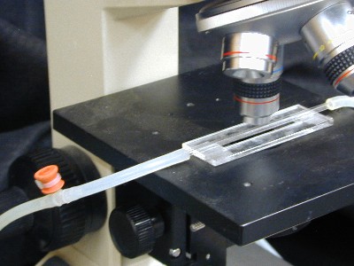
- In operation the flow cell is placed on the stage of a standard microscope under the desired magnification. Adhesion of cells and the growth of biofilm can be observed as a continuous process over time.
- Students may connect their flow cell to an aquarium by means of a peristaltic pump or a gravity feed system and observe the adhesion of cells and subsequent growth of the biofilm in real time.
In practice, the student should observe adhesion of cells to the inside of the glass wall, the growth of complex biofilm structures, the sloughing of biofilm masses and re-growth of biofilm in these denuded areas.
MATERIALS AND EQUIPMENT
Introduction
Four components of a basic flow cell reactor system are:
- the nutrient supply
- an access port
- the flow cell
- the waste disposal container
This exercise will describe the function and construction of the access port and the flow cell. Suggestions for nutrient sources and waste disposal will also be made.
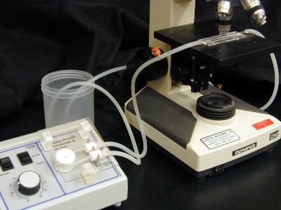
Figure 1. A flow cell reactor system
Material and Equipment for Flow Cell
Quantity |
Description |
| 1 | 1 x 3 x 1/8 inch Plexiglass® acrylic base. Many schools will have shops able to fabricate these. See student instructions. |
OR use |
|
| 7 inches | 1/4 x 1/4 inch clear acrylic rod stock (Part # 104015). This material costs approximately $ 0.20/foot. Available from Laird Plastics, www.lairdplastics.com. E-mail or call (800 610-1016) for a local distributor |
OR use |
|
| 1 | 2.5-3 inch metal washer purchased at a local hardware store. |
| 1 | square capillary tubing, 2mm I.D. or 0.9mm I.D. The Borosilicate square tubing is available from Friedrich and Dimmock, Inc. PO Box 230, Millville, NJ 08332. The 2 mm I.D. is Catalog Number BST-2-30 and the 0.9 mm I.D. tubing is Catalog Number BST-090-15. |
| 1 | triangular file |
| As Necessary | goggles |
| NA | super glue |
Material and Equipment for the Access Port
Quantity |
Description |
| 1 | T-barbed fitting connector, Cole-Parmer EW-30624-28, $8.50/25 |
| 1 | sleeve stopper Fisher Sci #03-215-5, $51.62/100 |
| 1 | polycarbonate tensioning tool, Cole-Parmer U-06830-07, $40.00/ea |
| 1 | 4" strap or cable tie Cole-Parmer U-06830-52, $17.00/1000 |
For General Assembly and Operation
Quantity |
Description |
| 1 | silicone tubing, cut into 3 pieces. (The length of these 3 pieces varies as needed for your application). This tubing is available from Cole-Parmer, use UA-96410-14 1/16" I.D. to fit the 2mm I.D. square capillary tubing ($40.00/25 ft) and UA-96410-16 1/8" I.D. ($45.00/25 ft) to fit the 0.9 mm I.D. capillary tubing. |
| 1 | Peristaltic Pump Fisherbrand, Variable Flow Model 13-876-1 Low flow, 0.03-8.2 mL/min $ 186.48 Modes 13-876-2 Medium flow, 4-85 mL/min $ 186.48 |
The Flow Cell
A flow cell is a device that permits the microscopic observation of the initiation and growth of a biofilm in real time. It is constructed simply from a piece of square capillary tubing mounted on a base. The flow cell is placed on the stage of the microscope and a source of microorganisms and nutrient is permitted to pass through the tube. Observation over time will permit the student to follow the various stages in biofilm development.
The tube that forms the reactor vessel itself is a square borosilicate capillary tube obtained from Friedrich and Dimmock, Inc. PO Box 230, Millville, NJ 08332. This tubing comes in a wide variety of sizes. The sizes found most useful are the 2mm inside diameter (ID) and the 0.9 ID. The 2mm ID is fairly sturdy and easy to handle but has a wall diameter too great to use the oil immersion lens of most microscopes. The 0.9mm ID tubing has a thinner wall thickness and can be used with oil immersion but it is very fragile and recommended only for students with some experience in this procedure.
Types of Bases
- The base of the flow cell can be made in several ways. If your college has a workshop or engineering department they may be able to fabricate the bases from 1/8 inch Plexiglass®. The bases we use are 1 x 3 inches (glass microscope slide size) with a slot centered through the center of the base of 3/8 x 2 inches. This slot provides an unobstructed light path to the flow cell from the microscope condenser (see Figure 3a). The bases were cut with a laser engraver owned by our engineering department.
A 4-inch piece of square capillary tubing, cut with a triangular file is super glued along the long axis of the base directly over the slot. - If these fabricated bases are unavailable, a serviceable base can be made from 1/4 inch acrylic rod stock available from Laird Plastics http://www.lairdplastics.com. For each base, cut two 3 inch long pieces and 2 1/2 inch long pieces. Assemble these into a rectangular frame (1 x 3 inches) and cement it together with cyano-acrylic cement (see cautions above and below). This frame can be used just like the plastic base described above (See Figure 3b).
- A third and very simple base can be made from a large metal washer (2.5 inches in diameter). The square tubing is simply glued to the top of the washer through its diameter (See Figure 3c).
Caution: Wear goggles while cutting the tubing, it can shatter. Use all appropriate precautions when using cyano-acrylic cement. It binds to fingers as well as to plastic and glass.
Caution: Cyano-acrylic cements like Super Glue and can bind fingers and skin in seconds. Use great care not to get any of the glue on your hands.
First Aid: Should binding to fingers or skin occur, immerse the affected area in warm soapy water and gently peel or roll the skin back and forth until the affected parts separate. Repeated washes in warm soapy water will permit you to peel off adhering super glue. In the event of cyanoacrylic contact with the eyes, seek medical assistance immediately.
The plastic bases have the advantage of being able to fit into the mechanical stage of a student microscope. The metal washer has the advantage of mass that makes it durable and stable.
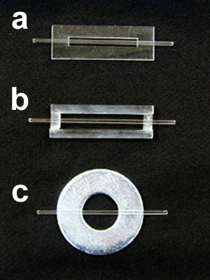
Figure 3. Three types of bases for flow cell construction
The Access Port
It is often desirable to be able to introduce or remove materials into or out of the system without compromising the sterility of the flow cell. An access port placed upstream and or downstream from the flow cell will meet this need.
A simple access port can be made from a T-barbed connector and a rubber sleeve stopper sold by Fisher Scientific. The narrow end of the sleeve stopper is pushed firmly over the stem portion of the T-connector. Once this is inserted into the line between the nutrient source and the flow cell, materials such as nutrients, other organisms, antimicrobics and dyes can be inserted into the system by clamping off the medium flow (up stream from the access port) and injecting the desired material through the access port and into the T-connector. Clamping above the port ensures that the material flows in the direction of the flow cell.
Materials can be removed down stream from the flow cell by inserting another such access port. To remove material, remove the rubber sleeve and allow the material to flow into a sterile container. Disinfect the T-connector with alcohol and reinsert the sleeve stopper.
Note: For a more secure fit, the cup of the sleeve stopper can be inverted back over the stem of the T-connector and this can be held in place with a 4-inch cable tie tightened with a tensioning tool. When tightening the strap around the base hold the sleeve tight to the T-connector so that the cable tie wraps around the stem below the barb. (See Figure 6 in the student instructions.)
Assembly and Use
If desired, all of the components of the apparatus may be autoclaved except the flow cell itself. The flow cell can be disinfected with alcohol.
It is a good idea to place the flow cell in a pan that can hold the entire volume of the culture or medium supply in the event of a leakage accident.
The cell may be set up in a recirculating or flow through system.
A recirculating system is among the easiest to set up. In this system a plastic tube from a culture (e.g. a hay infusion) is passed through the peristaltic pump. The access port is attached to the outflow from the pump and then to the flow cell. The effluent from the flow cell is directed back into the hay infusion. In this pattern no waste disposal container is necessary. An aquarium, a known culture, a pond water sample, or a sample from any natural water supply may be substituted for the hay infusion. Each will produce its unique biofilm in the cell.
A flow through system requires a source of inoculum, a medium supply and a waste container. The sterile flow cell system is connected to the medium supply and the medium flow is adjusted to the desired flow rate by adjustment of the peristaltic pump. After the system is filled with medium, the pump is turned off and the tube between the pump and the access port is clamped off. The culture of interest is injected into the access port and the system is allowed to incubate for a period of time for attachment of cells to the flow cell to occur, commonly over night. At this point the clamp is removed and the pump started so that the newly attached cells will receive nutrient.
Note: Caution and instruct students about the proper use of needles and disposal of sharps.
Note: Biofilms typically prosper at low nutrient concentrations, so 1/10 nutrient broth, TSB or LB broth is likely to produce a better effect than full strength medium.
ASSESSMENT / EVALUATION
Evaluation of the flow cell is made by the instructor’s visual inspection of each student's flow cell and its performance during operation.
FOLLOW-UP ACTIVITIES
Other ways of using the flow cell might include the following:- Place two flow cells in tandem each on its own microscope. Feed the two flow cells from a heavily overgrown aquarium with lots of algae and cyanobacteria. Cover one flow cell with aluminum foil to exclude light and illuminate the other. The illuminated flow cell should exhibit autotrophic organisms while the dark one should be exclusively heterotrophic.
- Once a biofilm is established, introduce a disinfectant, detergent or antibiotic through the access port and observe the results.
- Introduce a stain like carbol fuchsin or methylene blue through the access port and observe the result. Note this may damage the biofilm.
- Measure the length of “streamers” with an ocular micrometer and then increase the flow rate with the pump and measure the length of the streamer again. Plot streamer length as a function of flow rate. Now slow the flow rate while measuring “streamer” length. What happens to the length of the streamer as flow rate is increased and decreased? This simple procedure exhibits the viscoelasticity of biofilm extra polymeric substances (EPS).
- If your lab has a fluorescence microscope, stain the cells with acridine dye or with one of the dye combinations produced by Molecular Probes www.probes.com). They have fluorescent stains for determining if the cells are alive or not (Live/Dead BacLight Bacterial Viability and Counting Kit Cat # L34856), and for fluorescent Gram Staining - Live/Dead Bacterial Gram Stain Kit (L7005). Their catalog is on line and well worth a look.
Note: Since some of the reagents used in these fluorescent stains bind to DNA the possibility exists that some may be mutagenic or carcinogenic, although no data are currently available. See the Molecular Probes web site for precautions regarding use and disposal of these dyes. See http://www.probes.com/media/pis/mp07008.pdf.
REFERENCES
Detachment, surface migration, and other dynamic behavior in bacterial biofilms revealed by digital time-lapse imaging
Stoodley P, Hall-Stoodley L, Lappin-Scott HM
Methods in Enzymology, (2001) 337:306-319
Microscopy flowcells: Perfusion chambers for real-time study of biofilms
Palmer RJ Jr
Acknowledgments:
This exercise was This exercise was suggested by Dr. Paul Stoodley
Educational Program Curricula and Teaching Resources
Supported in part by the Waksman Foundation for Microbiology
Developed in collaboration with Dr. John Lennox, Penn State University-Altoona
© 1999-2008 Center for Biofilm Engineering, http://www.biofilm.montana.edu
