Measurement of Biofilm Thickness
Instructor Version (go to Student Version)
| Subject Area(s) | microbiology |
| Intended Audience |
high school biology, independent study/science fair, introductory undergraduate microbiology, advanced college level microbiology |
| Type | laboratory exercise |
| Revision Date | June 23, 2004 |
CONTENT
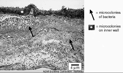
The thickness of biofilms is an important parameter for scientists and engineers to know because it is related to the rate of growth of the biofilm and the extent to which biofilms interfere with human engineered devices. The rate at which nutrients and antimicrobics penetrate biofilms is related to thickness, as is the rate to which they respond to antimicrobics like disinfectants and antibiotics. The degree to which biofilms interfere with the fouling of pipes and fluid delivery systems and interfere with the function of devices like heat exchangers is also due, in part, to the depth of the biofilm (see Figure 1).
This exercise describes a technique and apparatus by which students can measure the thickness of living biofilms in a non-destructive manner over time. Students may also gain a greater appreciation for the concept of refractive index as a result of the calculation one must make to improve the accuracy of these measurements.
PREREQUISITES
Students should be able to define a biofilm, describe the differences between biofilm (surface-attached) and planktonic (suspended bacterial cells) bacteria, and be able to describe why bacteria usually grow on surfaces. Students should have some understanding of the concept of light refraction and of the refractive index of transparent materials like air, water and glass.INSTRUCTIONAL OBJECTIVE
Depending upon age, nutrient concentration and the frequency of sloughing of film segments, a biofilm may vary in thickness from a few micrometers to several hundred micrometers. Although measurements of length and width are commonly made using ocular or filar micrometers calibrated to external standards (e.g. a stage micrometer), measurements of depth represent a more difficult task.Some microscopes are equipped with a measuring device attached to the fine adjustment knob. The old AO Spencer Microstar Series 10 microscopes, for example, have a series of graduations in which one complete turn of the fine adjustment knob advances the lens 200 µm. Since there are 200 divisions on the knob, each division represents an advance of µm. To calculate depth, a student could focus on the top of an object and then focus again at its base and record the number of fine adjustment knob divisions that pass the registration line. Unfortunately, all microscopes do not come so equipped.
In this exercise, when given an easily constructed apparatus, detailed instructions and an established biofilm, a student will be able to measure the optical thickness of the biofilm on a standard glass microscope slide or flow cell. Using simple mathematical relationships the student will then be able to calculate the physical thickness of the biofilm that differs from the optical thickness due to the refractive properties of the air – biofilm interface.
INSTRUCTIONAL PROCEDURES
- Copies of the student instructions will be distributed ahead of the class.
- The apparatus will be explained and demonstrated.
- If the teacher desires, she may have the students calibrate the microscope individually.
- Using the instructions given and the calibrations they have been given or have obtained themselves, the students will measure the thickness of various objects as assigned by their instructor. When enough experience on the microscope has been obtained, the student can measure the thickness of a biofilm they have grown or been given, either on a microscope slide or in a flow cell.
MATERIALS AND EQUIPMENT
Equipment
Quantity |
Description |
| 1 | microscope |
| 1 | metric feeler gauge (optional) |
| 1 | polar coordinate graph paper (8.5 x 11 in.) |
| 1 | card stock (8.5 x 11 in.) |
| As Necessary | thin wire |
| As Necessary | transparent tape |
| As Necessary | biofilm (in a glass microscope slide under a coverslip or in a flow cell) |
Construction of the Measuring Device
- Photocopy a sheet of 8 1/2 X 11 polar coordinate graph paper onto a piece of card stock (this is to give the graph paper sufficient stiffness to be used in this application).
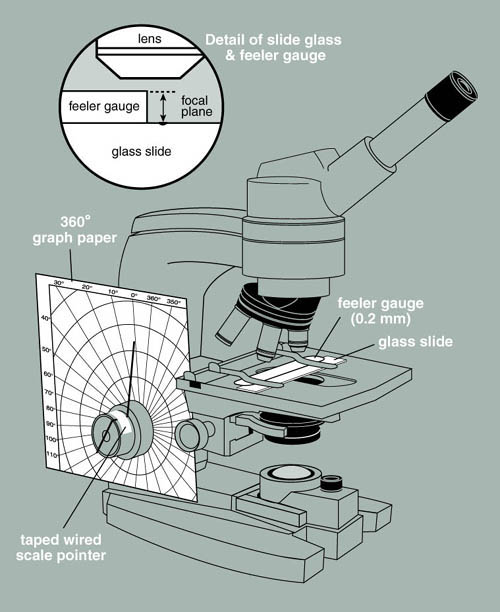
- Cut out the center of the polar coordinate graph paper so that it will just fit over the course and fine adjustment knobs of a microscope. You will probably have to trim the graph paper to make it fit the microscope as shown in Figure 2. Tape the graph paper to the microscope body so that it is held rigidly in place. If you choose an older microscope you may be able to dedicate an instrument to this application and not have to remake this apparatus each time it is needed.
- Make a pointer by bending a thin piece of wire so that it fits over the end of and through the center of the fine adjustment knob. The pointer end should extend beyond the knob and nearly touch the polar coordinate graph paper (see Figure 2). Fix the pointer in place with transparent tape. The degree to which the fine adjustment knob is turned can now be recorded in degrees of arc.
Calibration of the Measuring Device
- Obtain a metric feeler gauge from your local auto parts store, or if your campus has an engineering or physics department they may be able to supply one. Tightly tape the gauge to a glass microscope slide. This is a bit awkward but it can be done. The 0.04 mm gauge is a good choice. Place a mark on the glass slide with a glass-marking pen, right along the edge of the feeler gauge to give a clearly visible surface to focus on with the microscope.
- Mount the slide with the attached gauge on the stage of the microscope equipped with the polar coordinate graph paper. Make sure that the gauge is tight against the surface of the slide.
- Focus on the surface of the feeler gauge at its edge and record the reading of the pointer on the graph paper.
- Now focus down onto the mark you placed on the glass slide. Once again record the angle of the pointer in degrees. Calculate the degrees of arc difference between the first and second reading. This represents the degrees of arc proportional to 0.04 mm. If, for example, 82 degrees of arc moves the lens from the surface of the gauge to the surface of the slide, then 82 degrees of arc = 0.04 mm or 40 µm. Each degree of arc therefore equals 0.49 µm or approximately 0.5 µm.
Note: If a feeler gauge is not available a glass cover slip may be substituted. Most are manufactured to precise tolerances. Thomas Red Label #2 cover slips, for example, are guaranteed to be between 0.19 and 0.23 mm thick. Measuring one with a micrometer produced a reading of 0.21 mm. One can place a mark on the top and bottom of the cover slip in order to make focusing easier.
Correction for Differences in Refractive Index
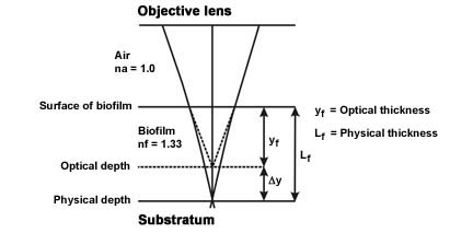
- The refractive index of air and the refractive index of the biofilm (95+% water) are different, therefore, the optical thickness and the actual physical thickness will differ. Since the refractive index of the biofilm will be greater than the refractive index of air, the actual thickness of the object will be greater than the measured optical thickness (See Figure 3).
- The physical length Lf ≈ kfyf where yf = the optical thickness measured and kf = a proportionality constant function of the refractive indices of the biofilm and air.
- Since the proportionality constant kf ≈ nf / na (Refractive index of the biofilm [nf = 1.33 or approximately that of water] divided by the refractive index of air [na = 1.0]) the proportionality constant = approximately 1.33.
- The actual length (Lf ≈ kfyf) is therefore the measured optical distance (yf) multiplied by the constant 1.33 (kf).
(Modified from Bakke and Olsson, see reference)
ASSESSMENT / EVALUATION
The students’ understanding of and skill in using this technique can be obtained by having students measure the thickness of known objects (cover slip, a human hair, etc.). Alternatively, students may be asked to calibrate the microscope against a known standard and their results can be compared with instructor generated calibrations.The students’ proper application of the refractive index correction can also be evaluated. The correction should not be applied, for example, if the object being measured is not mostly water.
FOLLOW-UP ACTIVITIES
Once mastered, this technique can be used in many instances in which the students are expected to take physical measurements of a biofilm or of any other object under the microscope.This measurement could be included as part of the “Bring ‘em Back Alive” semester-long project. It could also be employed to measure the thickness of biofilms made using the Static Glass Coupon Reactor or the Flow Cell described elsewhere in this collection.
REFERENCES
R. Bakke and P.Q. Olsson, 1986, Biofilm Thickness Measurements by Light Microscopy, Journal of Microbiological Methods 5:93-98.
Thanks to Paul Stoodley of the Center for Genomic Sciences (CGS) Allegheny-Singer Research Institute in Pittsburgh, Pennsylvania for submitting corrections to the original exercise.
Educational Program Curricula and Teaching Resources
Supported in part by the Waksman Foundation for MicrobiologyDeveloped in collaboration with Dr. John Lennox, Education Editor, Penn State Altoona
©1999-2008 Center for Biofilm Engineering, http://www.biofilm.montana.edu
